Module 3 (Server Managment & Networks)
 Photo by Taylor Vick on Unsplash
Server Managment & Networks
Virtual Machine
What is a Virtual Machine your probably asking? A Virtual Machine or short VM is a logically seperated “computer” on hardware basis. That basically means you can for example run multiple Operating Systems (OSes) on one PC/Server. Normally that’s made through a so called “Hypervisor” software.
There are two types of hypervisors:
- Type 1 hypervisor
- This type is built/coded directly on the hardware
- Doesn’t need a OS to run
- Type 2 hypervisor
- Is running on a “host” OS
- have to get premission for seperating the hardware resources from the OS
- accessable through the OS GUI
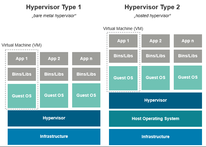
Hypervisor setup of type 1 & 2 / Source: mkaschke.medium.com
Big companies like Amazon, Google or Microsoft normally use type 1 for they VMs on their servers. It’s more efficient (thourgh direct access to the hardware resources), faster and more secure (less attackin potential without OS).
In contrast the type 2 hypervisors are much more convenient to handle because you can call them over an OS (and their provided GUI). They are commonly used for testing purposes like developing use-cases, security issues or try out programs on different OSes without affecting the host OS through the seperated hardware allocation.
VMs are used all over the place in modern IT because they have so much positive aspects and advantages compared to traditional hardware constructions:
- parallel operations of OSes (guests)
- better capacity utilisation
- encapsulations with their own processes and storages on one physical infrastructure
- savings in relation to maintenance and administration
- cost efficient through less physical resources and space
- easy to recover data as well as transport of the virtual machines
But there are also some negative aspects which have to be considered:
❌ Overhead (meaning: IT resources for example calculation time, storage, bandwidth) through hypervisor which consumes resources by himselfe
❌ Use at the same time can cause shortages through shared hardware
❌ Single Point failure (attacks thorugh hyperviser software itselfe)
❌ Unclear legal situation of use-cases
Setting up environment
To be able creating and using a VM you first need to set up an environment for it. In this module I use Oarcle Open-Source project VirtualBox to load and handle the VMs, Vagrant for setting them up and using the VM terminal and Secure Shell (SSH) to have a cryptogarphic network protocol (in our case we don’t need that in first line because we don’t use a remote VM). It helps us to access the VM faster and efficiently.
Firstly I installed Oracle’s VirtualBox and after that I intalled Vagrant as well. To check if it’s installed I quickly checked with the version control:
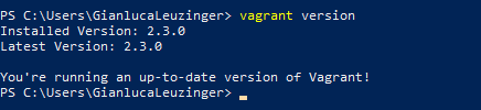
Checking if Vagrant is installed with Powershell
After that I had to initiate it with a Vagrant file. Then after starting Vagrant up I already encountered an error because firstly there was an overlapping of the Windows preinstalled VM manager called Hyper-V and the manually installed VM manager VirtualBox. So I had to disable the one from Windows with some commands in the CMD.
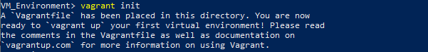
Initiate Vagrant with Powershell
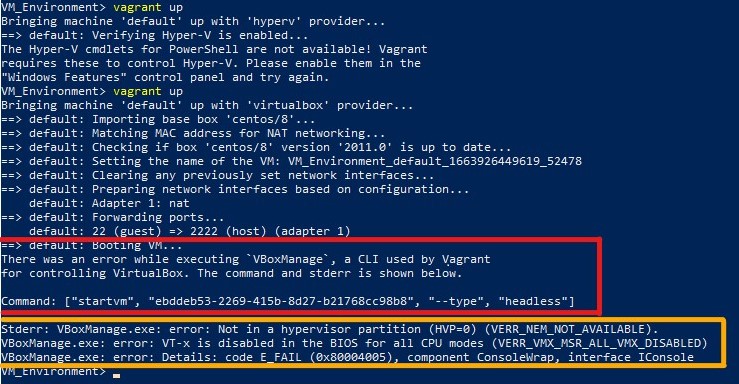
Error 1 (red) and error 2 (orange) caused by wrong settings
The next error was generated because the BIOS has the Intel Virtualization technology disabled per default. Therefore I had to log in to the BIOS and enable it.
My last step then was to make a SSH config file in which I had to copy some data in relation to the host. Then I was finally able to start my first VM an access the Linux controlled terminal via Vagrant over the Powershell terminal. That’s what it looks like:
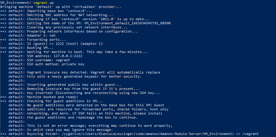
Starting Vagrant up after fixing the errors
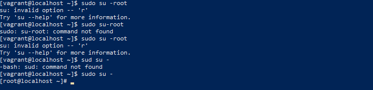
Linux terminal from the VM with root access
Linux controls
To be able using the terminal of the VM I first need to refresh my knowledge in relation to the commands used in Linux. There are quiet a few and they help you to guide yoursekfe effortlessly through everything and speeed up the processes without a GUI.
The first ones I learned were the following:
- echo -> outputs strings who are passed to it in the form of arguments
- pwd -> stands for print working directory
- ls -> stands for list contents contained in the directory/folder/file
- cd -> stands for change directory and is used to move between the driectories
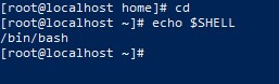
Check which Shell is used
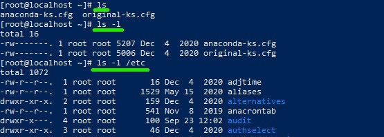
Different listing methods with ls
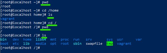
Moving around between directories
But there are more which you can use to easily navigate through the Linux terminal:
- An important command is man to show all manuals of the Shell based commands
- They explain what attributes, arguments a command has and how they work
- You can a search with / + keyword
- Run through the results with n and get back to the first one with >
- Press q and enter to exit the manual

Command to call a manual page
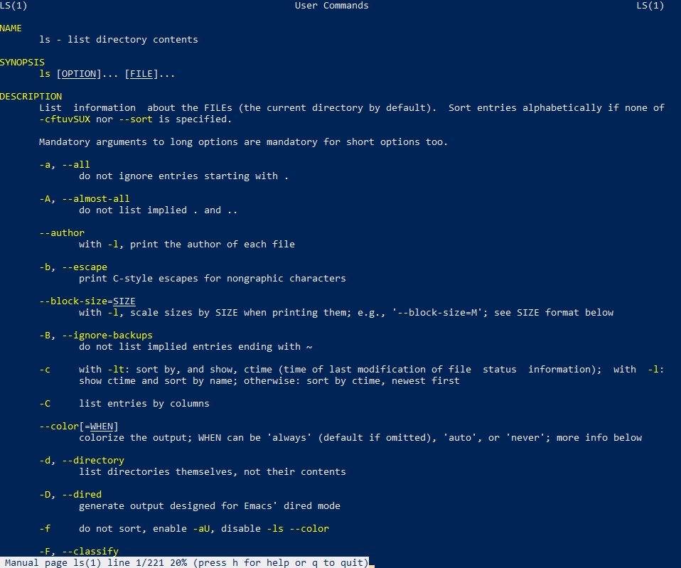
How such a page looks like
- Another very important command is mkdir which creates a new directory (make directory)
- rm -> remove a directory/delete it and with the argument rf you force the whole folder to get deleted
- v -> shows you every step it makes during the execution
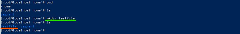
Creating a new directory
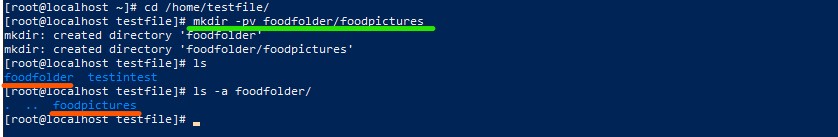
Creating a new folder with every step shown

Deleting the newly created directory
- Further you can copy and move files
- cp -> copy a file
- mv -> move a file
- touch -> create a file
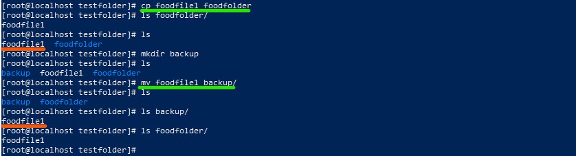
Copy a file and moving it into another folder
VI (Six/Vim) editor
The VI editor is normally used as a fast command-line based IDE to create files. For experienced users you have the abilities navigating really fast through everything without using a mouse or GUI.
The most common commands to use this are:
- Ctrl s (Ctrl q) -> to freeze the page (to normalize it)
- Ctrl c -> to cancle something
- ZZ -> save and exit
- :q! -> discard all changes and exit
- :w -> save but dont exit
- :wq -> save and exit
- cat (concatenate) -> to let you see whats in the VI file
- less -> to get a more comfortable sight from the VI file
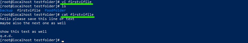
Created a new VI file with some text
Mastering the VI editor can be an extremly valuable abilitie but is also quiet difficult at the beginning and needs some time to get used to it. For all commands you can use a cheat sheet like this one: Cheat Sheet VI
Permissions and File Manipulation in Linux
To be more efficient in how you find files and search for things in a Linux terminal you can use some file manipuations tricks:
- Use ‘*’ to search anything
- Use ‘?’ to replace one letter or ending
- Use ‘[ ]’ to replace a range of letters or also specify a range of digits
- Use ‘[^]’ to make a reversed search
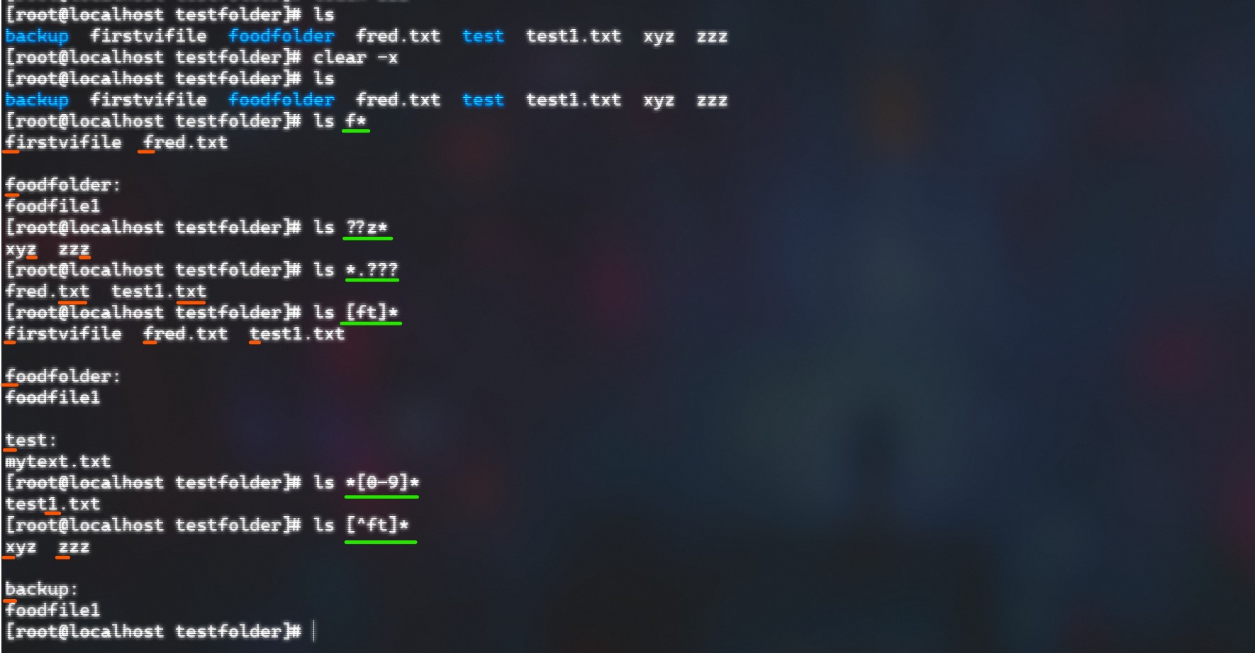
Some example (green -> command) / (orange -> results)
Linux also handles permissions in a special way. There are three premissions a file can have:
- r -> for reading permission
- w -> for writing permission
- x -> for executing permission
- While a ‘-’ represents there is no permission for this person/group
- At the beginning of a -l command a ‘-’ has the meaning of a normal file while a ’d’ stands for a directory
And this permissions can be owned by three different kind of owners:
- The ‘owner’ which represents a single person who owns the file
- A ‘group’ wich represents that every file belongs to a specific group of owners
- For everyone else that doesn’t belong into this two categories there is the state ‘others’
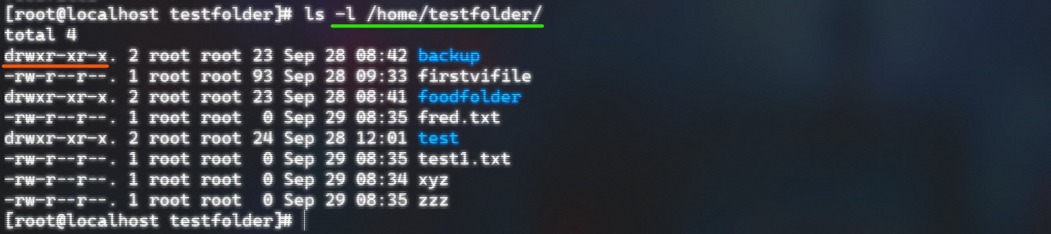
The first 10 characters showing the permissions of all three categories
But the permissions can also be changed with the command ‘chmod’ which basically stands for “change file mode bits”. The command consists of three different arguments:
- For whom do we change the permission -> [ugoa] (user, group, others, all)
- Grant or evoke -> ‘+’ / ‘-’
- Which permission we want to change -> [rwx] (read,write,execute)
- But you can also shortcuts (octal number bits = 0, 0, 0 (0 - 7 versions of r, w, x))
- Same with works with directories but to see the changes make ’ls -ld’
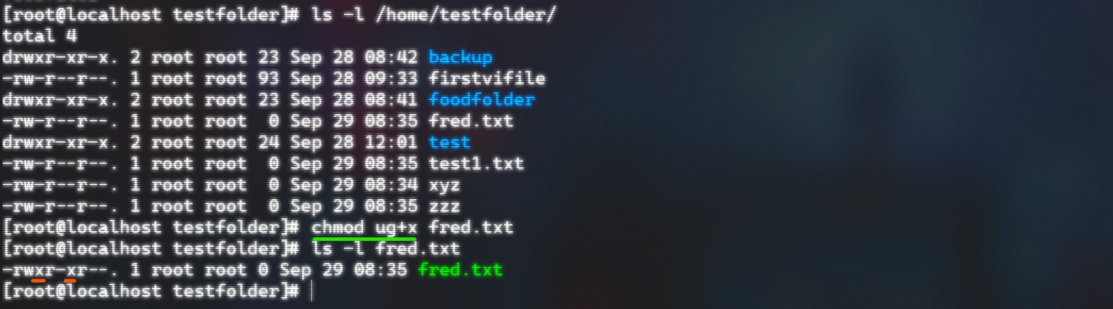
Changed execute permissions for the ‘fred’ textfile
Normally only two person can make changes directly with the file permissions or directories: that are the owner and the root user (superuser) like i’m at the moment in my VM.
Specific information gathering
Another helpful commahd is ‘grep’. It does show you particular lines of data which you specified through a character pattern(powerful tool to search for specific informations). Here is a list of possibilities to use egrep: '
- ‘.’ -> single character
- ‘?’ -> character matches 0 or 1 time only
- ‘*’ -> " 0 or more times
- ‘+’ -> " 1 or more times
- ‘{n}’ -> " exactly n times
- ‘{n,m}’ -> " at least n times and not more than m
- ‘[abz]’ -> one of those included
- ‘[^abz]’ -> is not one of those included
- ‘[a-g]’ -> in the range of this
- ‘()’ -> several to behave as one
- ‘|’ -> logical OR
- ‘^’ -> beginning of a line
- ‘$’ -> end of a line
You have the possibility to combine as much as you want.
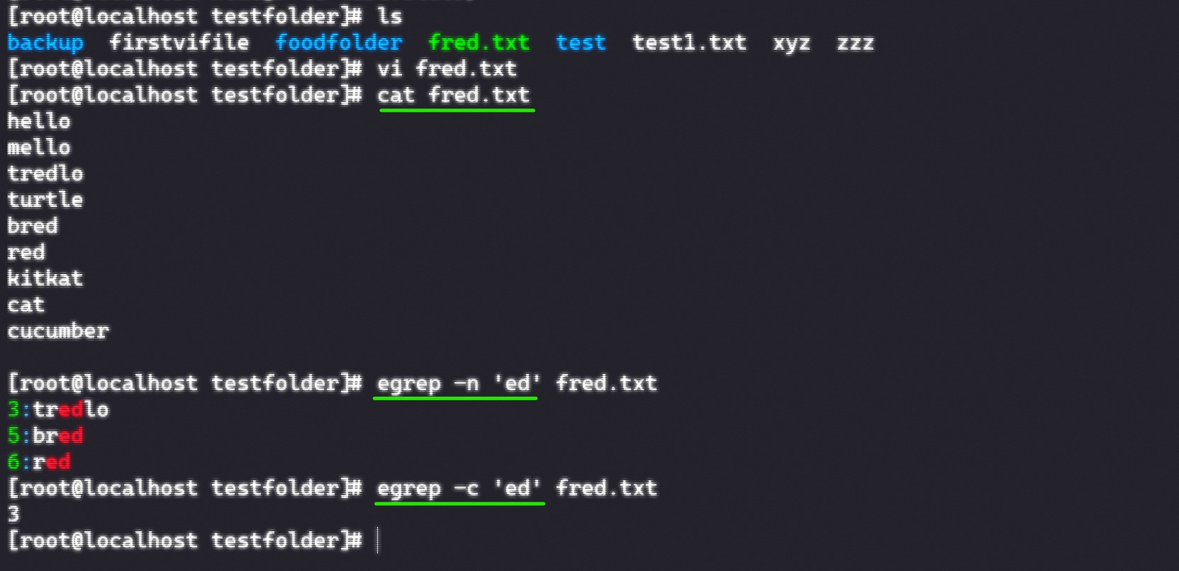
Egrep command used for a text file
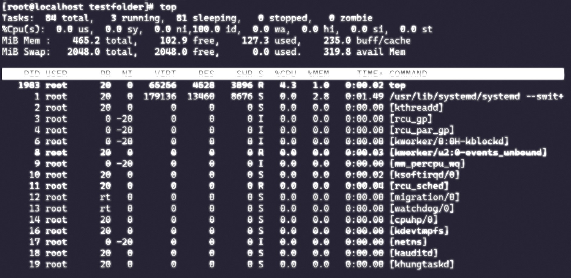
Snapshot of the RAMs processes
Red Hat Certification Systemadministrator Linux 8 (RHCSA 8)
Basics & Environment
For this section I will mainly list the most relevant commands you use to handle the different topics that are covered in the manual which I thought are the most useful/important ones to remember after completing all need chapters. It would just be to complicated to show everything that is done on the terminal to understand which processes do what and how. But not included are the commands that I already mentioned above which are just to use Linux terminals in generall.
Shell Enivronment & File System Hierarchy
- env -> displays the currenc environment and all standard variables and how they are defined
- man -k
-> searches through all man pages in which the keyword is used and shows them - mount -> gives you an overview over all mounted devices
- findmnt -> shows the relationships
- df -hT -> you get a closer look at what diskspace is still left
Users and Groups
- exit -> exits a user you were logged in
- sudo -i -> enter root mode
- adduser/userdel
-> adds / deletes a user - sudo passwd
-> changes the password of the user account - su
-> switch user (subshell) - id
-> shows all groups in which the user is - sudo tail -n 10 /etc/passwd or /etc/shadow ->
- chage -l
-> shows the aging of the user - usermod -aG wheel
-> adds the user to the administrative group which can execute commands with sudo - whoami -> shows which user you are currently using
- groupadd
-> adds a user to a group - sudo tail -n 10 /etc/passwd or /etc/shadow -> shows hashed passwords (only with root rights)
Network Configuration
- ip addr show -> lists all network interfaces from your computer
- ip (-s) link show -> lists the state of the network interfaces (current statistics for packets transmitted and received)
- ip route show -> which router is used (ip of default router should always be on the same network as the local ip of the PCs networkcard)
- ss (-lt) -> availability of ports on your server (lists all listening TCP ports)
- nmtui -> provides a GUI to change your hostname
- hostname
-> changes hostname - hostname -> shows the hostname
- FQDN -> fully qualified domain name which consists of a hostname and DNS domain in which the host resides
Yum
- yum search
-> searches for packages with that word in it - yum info
-> provides more information about the package - yum remove -> deletes an already installed package
- yum list
-> list the installed packages - yum repolist ->
- yum update -> updates every package on the system
- yum group list (hidden) -> list the different package groups
- yum history -> shows everything that got installed or deinstalled as well as updated through yum
- yum history undo
-> to undo a specific task made with yum
Logging
- systemctl status -> monitors the service status
Networking
Every data package that you want to transmit from one PC to antoher without using a hardware storage which has to be transported (like f.e. an USB) has to be sent over networks. The biggest network today is known as Internet. Through the connection of thousands and millions of PC’s it is possible to transfer data in seconds from one place in the world to another on the other side of the globe.
Normally we differentiate between the size of such networks. Therefore they are calle differently:
- PAN -> Personal Area Network (normally short distances even over cable)
- LAN -> Local "" (usually used with Ethernet or WIFI > WLAN)
- WAN/GAN -> Wide/Global "" (Network over large distances usually referred to as the Internet)
Network models
Network models have been made to understand the whole process which is needed for a data package from sending until receiving.
OSI-Model
OSI stands for “Open Systems Interconnection” and is a conceptual framework for how applications communicate over a network. It conists out of 7 layers about which I’m going to explain a bit more in this section. The OSI model in general acts more as an assistance to understand network transmissions but it is not implemented on the Internet itselfe (rather the TCP/IP model is used for this). The 7 layers are (from top to bottom):
- application layer
- presentation layer
- session layer
- transport layer
- network layer
- data link layer
- physical layer
Application layer (7)
This layer is the most “known” layer by end users. It provides an interaction with the data through network services over protocols like for example HTTP. An application that uses this kind of protocol are our modern webbrowsers (Firefox, Google Chrome etc.). Other applications that also use this are messengers or emailproviders.
Presentation layer (6)
The presentation layer is mainly used to “translate” the data which is need for the applications to be sent over the network. Therefore the three main goals of this layer are:
- Translation
- Encryption/Decryption (ciphertext/plaintext)
- Compression (reduces bits needed to send the data over the network)
Session layer (5)
In this layer the main focus lays on the responsibility of establishing a safe and smooth connection. It ensures that two systems can communicate and have a constant connection which is authenticated (if needed) or can also be terminated.
Transport layer (4)
In this stage of the OSI model the completed “messages” (data) get sent from one client to another client through the internet. For this it uses TCP (Transmission Control Protocol) UDP (User Datagram Protocol). The layer coordinates how much, how fast and where to send the data. It also adds a header with a port number so that the message is delievered to the correct process.
Network layer (3)
Within this layer which is normally implemented by devices like routers the routing and logical addressing takes place. Here it gets determined which is the shortest route and which exact device has to be accessed (mapping of IP addresses -> Address Resolution Protocol (ARP)).
Data link layer (2)
Data Link Layer or DLL is responsible to send the message without errors to the correct host in a network. For this it has two sublayers called LLC (Logical Link Control) and MAC (Media Access Control). Keypoints therefore for this layer are physical adressing, error and flow control.
Physical layer (1)
The physical layer is the lowest of all layers. It provides everything in terms of bits like bit synchronization or rate control and also defines physical toplogies of the nodes in a network.
TCP/IP-Model
The TCP/IP model is the main model used today. It differentiate to the OSI model mainly in the layers 5-7 which are summarized in one layer called “application layer”. Layer 1 to 4 are for the most part the same as in the OSI model with the most importance in layer 2 and 3 from where also the name comes. Because in layer 2 the main protocol used is the Internet Protocol (IP) while in layer 3 it’s the Transmission Control Protocol (rarely also UDP for smaller data packages).
Network Hardware
Hub, Switch & Router
A hub is used to connect different devices through ethernet in the same network. A switch does exactly the same thing as well but in contrast to the hub it is smart. While a hub sends all packages which it receives from one port to all other ports as well a switch remembers the MAC addresses of a certain device and only sends the data from one to another (the chosen one).
Routers on the other hand do not connect devices on the same network like hubs or switches they connect different networks. So if data packages from the internet are demanded by the own network they filter out the data and directs them to the switch. But if the router receives data which isn’t for his network he sends them further to another router/network.
Modem, WiFi-Router & WAP
Even though lot of people think a modem is the same as a router it is not. While a router filters data from the internet for your specific requests or sends them into the interenet a mode brings the internet to your home/buisness. It provides a constant internet connection trough a ISP.
This comes from the two different signals that are used (analog signal from outside, digital signal from computers). For this reason the name modem was creadted (MOudalte, DEModulate). But today most routers include a modem in their hardware. There are also two different modem connectivites. Cable modems -> mostly used by television providers or DSL -> mostly used by telephone providers
The difference between a WiFi-Router and a WAP (Wireless Access Point) is that a WAP normally is used for extending the wireless signal in a building and much more handable for a big amount (only one administrator setting changes settings for every device) while WiFi-routers work like a normal router just wireless.
Firewall
A firewall basically means that you can prevent your network from malicious traffic/data. It can be for your whole network (network-based firewall -> can be stand-alone, cloud-based or router-integrated) or just for one PC (host-based firewall -> installed on a computer). With rules that gets defined by the administrator the firewall checks data with specific filters.
In the rules are simplified splitted up into a few basic categories. A permission category, IP addresses, protocols, destinations, ports, domain names, programs or key words. If a data fullfills every filter it can pass the firewall and reaches the devices in the network.
Ports
Ports are logical connections that are used to exchange program or service informations. Port numbers range from 0-65535 while they are splitted up into 3 categories.
- 0 - 1023 -> System/well-known ports (f.e. 80 for http, 21 for ftp etc.), server-based
- 1024 - 49151 -> user/registered ports, server-based
- 49152 - 65535 -> dynamic/private ports, client-based
IP
IP stands for Internet Protocol and is one of the most important protocols in todays internet. It makes it possible to cut the data into smaller packages. With the attachment of an IP address in the header it makes it possible that the packages can take different routes (whatever is the most efficient) and still finds is way to the right Server/Client.
Today we normally use IPv4 (Internet Protocol version 4) which consists of 4 octets of bits shown in dezimal numbers to make it more understandable for us humans (as an example 142.250.203.100). But because already before the century change it was clear that this range of 32 bits will not be enough. So they came up with IPv6 (consists of 128 bits). Those addresses are normally represented in more hexdecimal style (example would be 2a00:1450:400a:808::2004).
They bring a lot of advantages with them but because these two addresses can’t communicate with each other it is only slowly emerging into our daily buisnesses/applications. The bigger address range makes it possible to give every device a unique address which can be sent information to from the internet (this even without using NAT(Network Address Translation)).
In networks normally the first IP address of the network (for example 192.172.156.1) is defined as the Default-Gateway (where data is sent through a router out into the internet) while the last address (192.172.156.255) normally stands for the brodcast (gives a signal to every device in the network to locate a specific one).
TCP/UDP
The second protocol that was authoritative for creating the TCP/IP model was the Transmission Control Protocol. It makes it possible to have a steady connection to send packages without loosing information. While TCP numbers the packages UDP doesn’t. If something is sent through TCP and wasn’t received by the receiver, he can just send a message which numbers are still missing and the protocol makes sure they are sent again. In comparison UDP is more used for data that can be lost and the receiver doesn’t has to agree on receiving data (permanent flow).
Subnet mask
Subnets are usually made that if a lot of computers are used in one network are 1. not sharing the same information or 2. don’t overload the network with bordcast requests. A normal subnet mask looks something like this; 255.255.255.0 . This basically means that the first 3 octets are used for the “network” portion and the last octet is used for the “host” portion.
With this you have a local network that can use the addresses from f.e. 192.192.167.2 - 192.192.167.254. This means if you borrow a bit of the subnet mask so 255.255.255.128 it gives you 2 networks with 126 hosts in it.
There is also another presentation type of subnet masks (192.168.1.0 /24) which is called CIDR(Classless Inter-Domain Routing). The slash just means the amount of bits that is used for the subnet masks so for /24 it would be 24 bits -> 255.255.255.0.
Internet connection through protocols
The four main things which have to be set up by a computer (host) to have communicate with any other computer on the internet are the following 4 things:
- IP address -> Identity on the internet
- Subnet Mask -> Size of the hostnetwork
- Default Gateway -> IP address of the router
- DNS Server IP -> Server needed to translate domain names to IP addresses
With those four settings set up every electronical device (PC, handy, printer etc.) can communicate through the internet. But to process, send and receive all the different datas correctly there are different protocols. A protocol is basically a set of rules and messages that form an Internet standard. I will list a few of them here:
DHCP
DHCP stands for Dynamic Host Configuration Protocol and is for the above listed specifications for an internet connection one of the most useful protocols. Without this protocol you would have to set up this configurations every time you connect with another network like a WIFI at your local coffee shop. DHCP enables us to let this manage a server.
Every time you connect to a new network your device send a DHCP discover message and asks for some predefined configurations meanwhile the DHCP server sends back an offer and provides for you IP/SM/DG/DNS. This is why it is called dynamic and not static. A static IP address would be that you have to assign the IP address every time manually.
Important to know that there are two states how a DHCP server manages the distribution of IP addresses. The first state of IP addresses are so called leased addresses. In this case the DHCP server only gives the devices an IP address for a specific amount of time. If the device leaves the network the IP address for this specific device will be deleted and can be rent to another device. If the device still remains on the network it has to send a request for renewing the lease.
The other state is called a reserved state. This is commonly used for less mobile devices like printers or routers etc. They normally stay in a network for a longer period of time and get assigned to a specific IP address so they don’t have to renew their address every time their lease would run out.
ARP
ARP stands for Address Resolution Protocol and resolves an IP to MAC mapping. The protocol therefore sends out a ARP request from one device (asks for the MAC address of a specific ID) and gets an ARP response from another device (host of the specific IP address sends a MAC address back).
HTTP(S)
HTTP stands for Hyper Text Transfer Protocol which uses HTML (Hyper Text Markup Language) files to display a website on a webbrowser. For this the client makes a get command to receive an OK as well as the HTML file for a website he requested from a server.
Later HTTPS (Hyper Text Transfer Protocol secured) was created through the usage of other protocols like TLS (Transport Layer Security) or SSL (Secure Sockets Layer). This basically means the data transferred by the HTTP protocol can be secured with TLS/SSL. This creates a tunnel through which the data is getting sent that the data can get changed while traveling.
FTP
FTP is also called File Transfer Protocol and is based on a Server Client architecture which are sharing files between each others.
SMTP
Also called Simple Mail Transfer Protocol is also used for a SCA and therefore a client and a computer can exchange emails.
DNS
DNS or also called Domain Name System is used to make IP addresses more readable for humans. So instead of using an IP address that looks like this 198.170.246.19 and type this into a browser search bar we can just enter a so called URL (Uniform Resource Locator) like for example www.google.com.
To handling this our computer first sends a request to an ISP (Internet Service Provider) if this server knows the address we are requesting. If he doesn’t know it is handled through DNS resolution (DNS resolver). To know how this works we take a quick look at this example graphics:
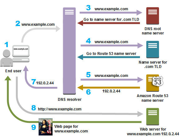
Example of a DNS request from a user / Source: amazon.com
- First you normally ask your ISP
- Secondly the DNS resolver from your ISP will contact one of the 13 DNS root servers (.) which are placed all over the world
- He won’t know the URL as well but will redirect you to a TLD (Top Level Domain) server and give you the IP address of the correct one
- Same for this server will happen again and he will redirect you to another server / ANS (Authoritative Name Server).
- Finally this server will know the address and gives back an IP address for the correct webpage to your ISP
- After this first DNS lookup happened the URL will be cached to get a faster result when it will be used again by someone
SMP
Server Message Block is a network protocol for file, printing or other server services used in data centers.
SNMP
SNMP stands for Simple Network Management Protocol and it’s goal is to control and monitor different networkelements from one central station. It additonally rules the communication between the elements and the monitoring central.
CMD tools
Some good tools/commands to check on all this different data you need like IP addresses (IPv4, IPv6), Subnets, DNS Server etc. are:
- nslookup (checking if DNS resolution still works)
- ipconifg (shows you all the information about IP addresses your PC needs)
- ping
(to check if your PC has an internet connection) - netstat [-n, -a] (shows the current network statistics like connections that are open and port numbers used)
Cisco Packet Tracer
The Cisco Packet Tracer is a software to visually present networks how their are built up and how they work/send messages. In the following section I show some pictures of how I worked with it and what my results were for the tasks given.
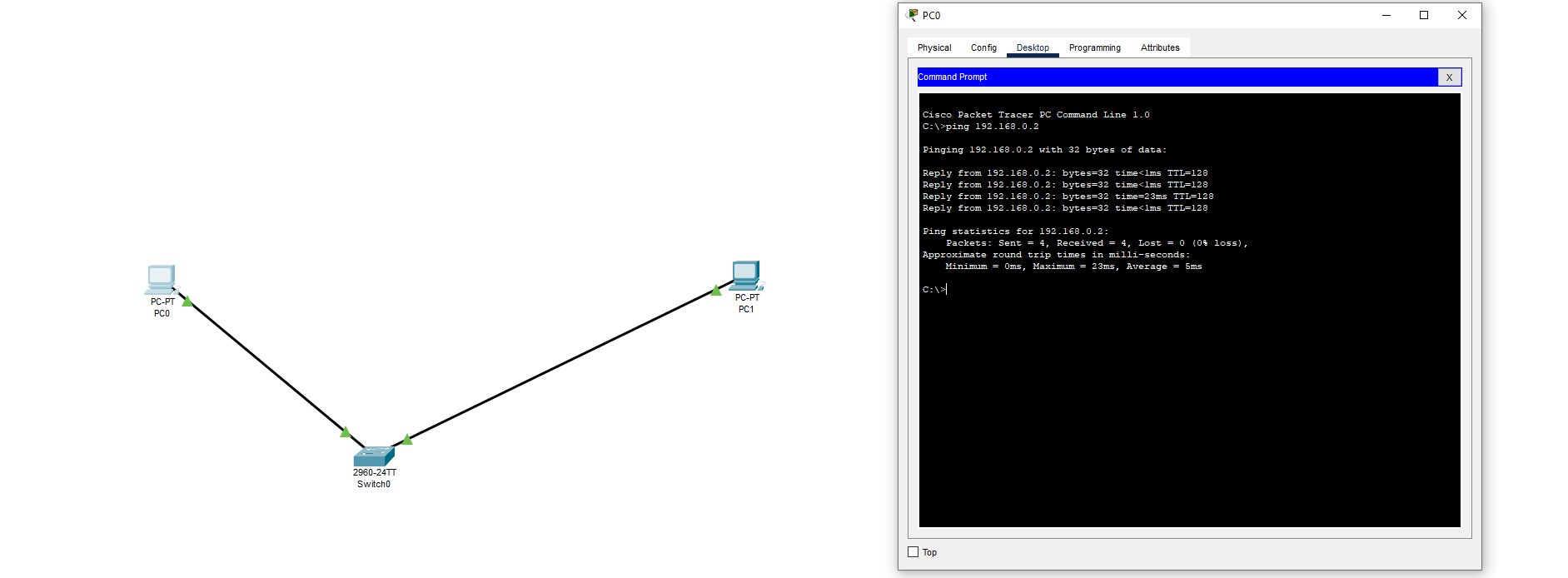
Ping another PC over switch
After the little first implementation and the pinging worked I continued with the use of a DHCP server. In it you were able to configure different pools as well as the address range of this pools.
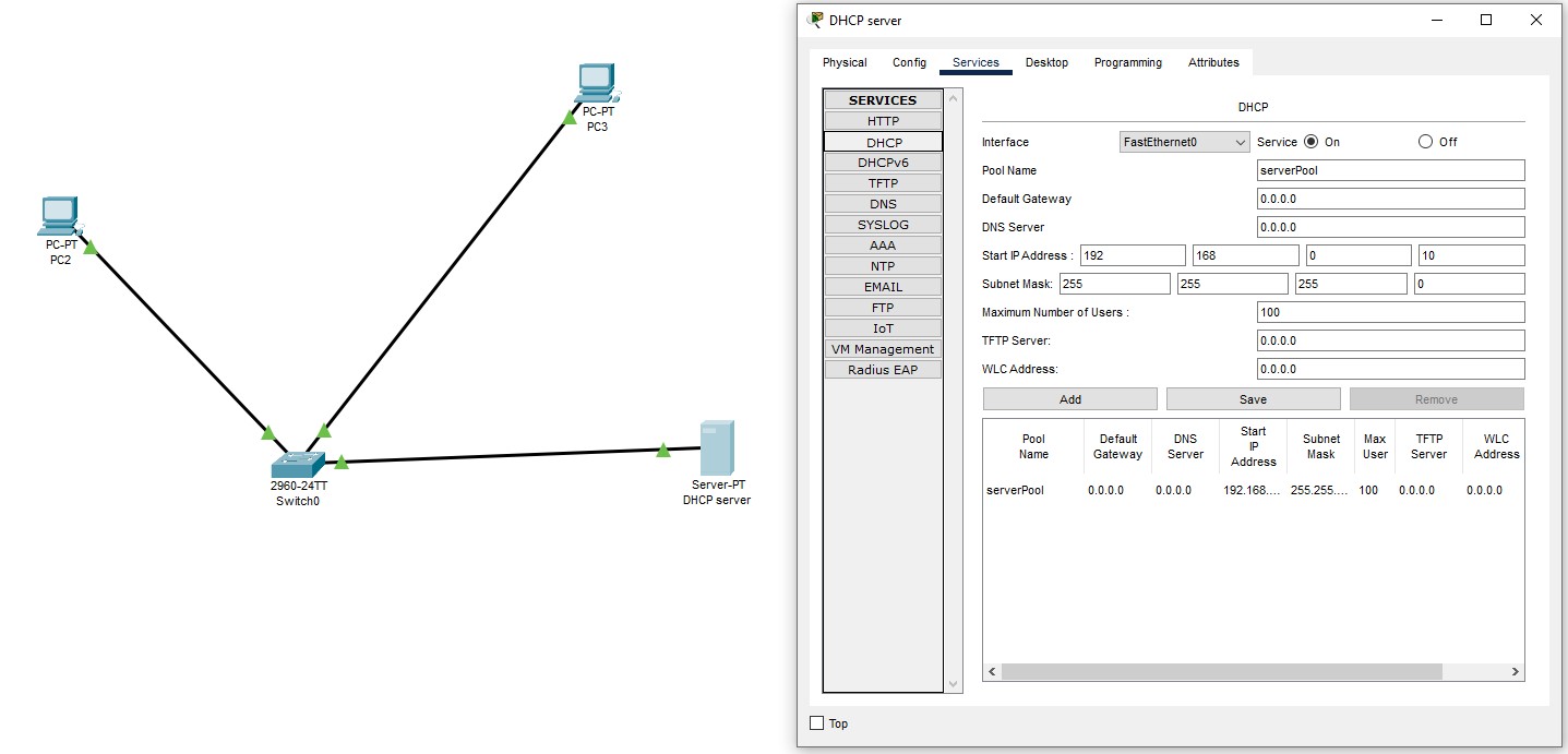
DHCP server connected to 2 PCs
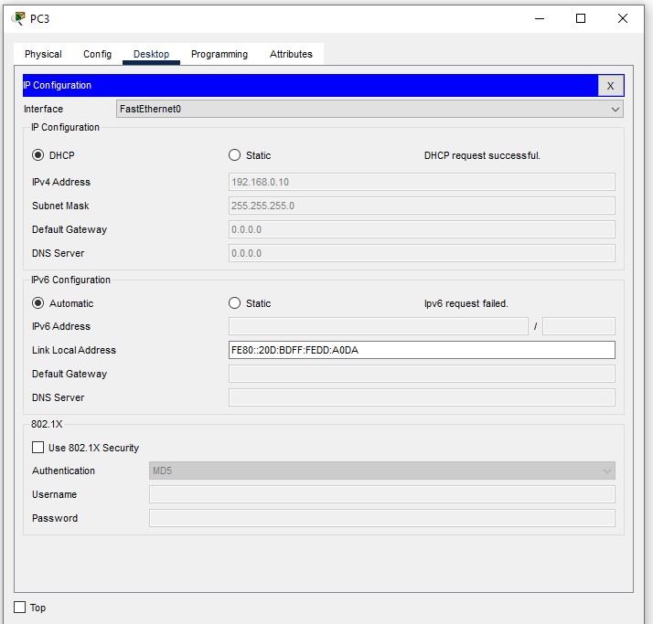
Successful IP dstribution to a PC
After I then got more used to the Cisco Packet Tracer I went over to the bigger exercises. The first one was to connect a DHCP to 2 networks over which one was connected with a switch and the other one with a router (client/developer network).
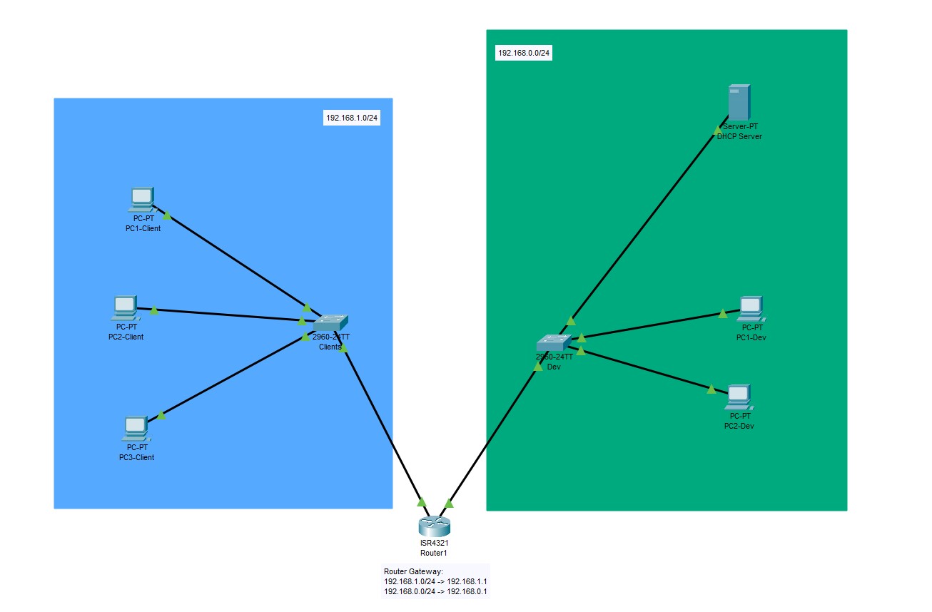
Client & Dev network connected to DHCP
The problem I was facing with the router was that IP distribution hosted by the DHCP server wasn’t sent over to the other network. It worked in the local dev network but not in the client network.
I found out that there was a little tricky misunderstanding when you use the Packet Tracer. In the real word all these servers and routers normally don’t have GUIs implemented. But for example and understanding reasons to make it more clear for beginners this application has implemented some GUIs.
But to configure which pool is used for the client network or in other words what the router has to forward you are only able to configure in the CLI (command line interface). With this hint I was then finally able to make it work.
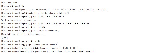
Configuration of the DHCP server in the router CLI
For further steps in the exercise I had to expand the networks with some other stuff like: Wireless AP, a Laptop connected to the WAP, Webserver, DNS server, second router and a printer.
The difficulty in those expandation steps was that you had to route the traffic from one network to the other correctly because you now had more then one router which meant for one of the 3 networks had to be 2 different gateways to the outside. But all devices in every network had to be able to get an IP from the DHCP, know URL/device names through the DNS server and can ping the printer.
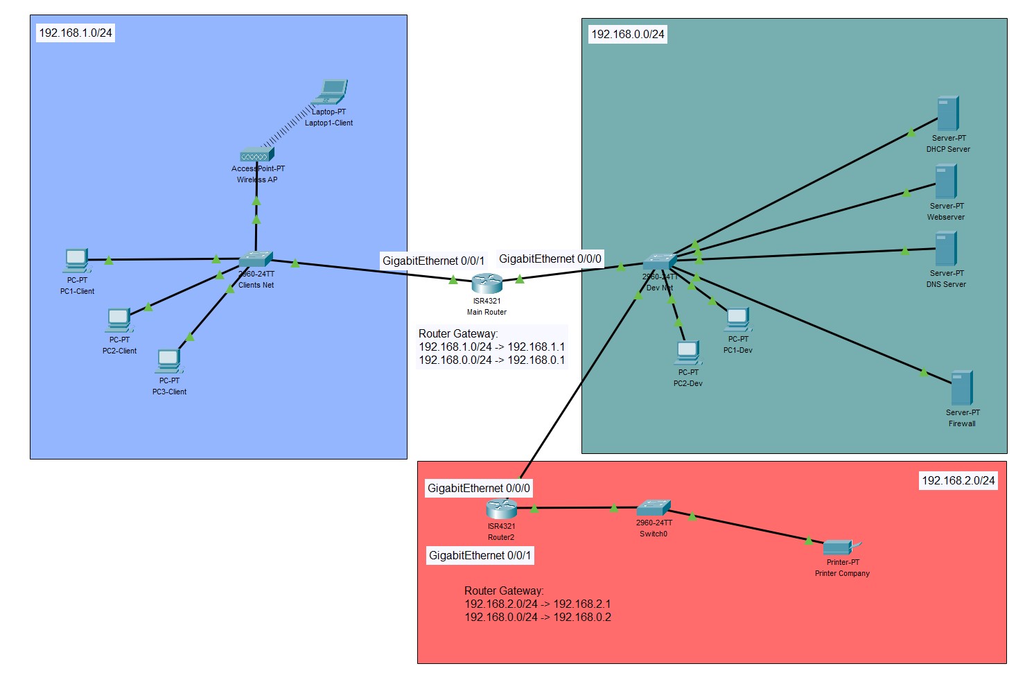
Completed exercise with everything implemented
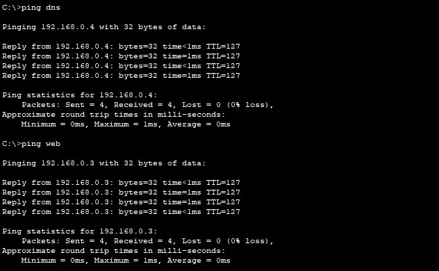
Capable to ping both servers (DHCP & DNS)
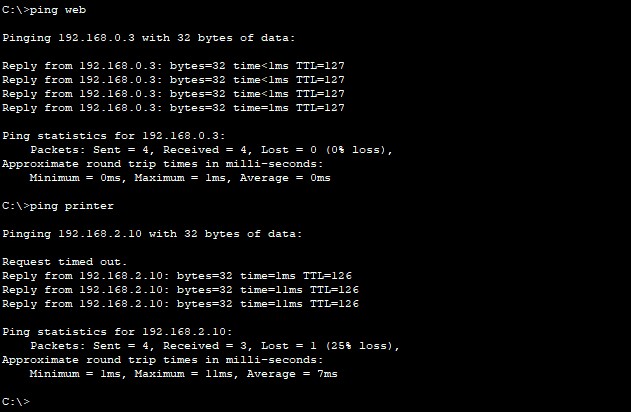
Capable to ping the printer
The second task then was to make a bigger lab (more likely built in regard to the reality). There had to be 4 different networks with each network being able to have at least 1000 host IP addresses available.
From this 4 networks (Office, Production, DMZ and Servers) the office network had to be subdivided into 3 subnets (IT, Employee and Printer). The whole traffic should go over a firewall which then receives, routes and checks the traffic correctly. Again it should include different servers.
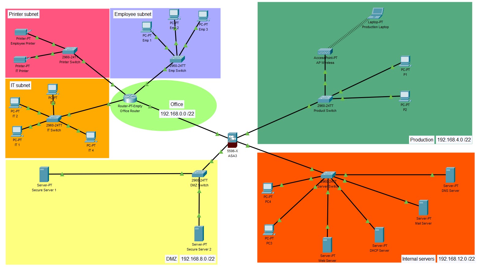
Completed exercise with the 4 networks
But to achieve this I had to overcome a few harsh problems. Main reason for these problems was that I hadn’t good resources because the Cisco Packet Tracer itselfe hasn’t a very good documentation. Therefore it was really hard to even find the correct commands for each different configuration in the CLI.
The hardest part was to configure was the firewall. Into it I had to implement the 4 different networks, the routing (which first didn’t worked with static routing so I afterwards switched to RIP routing), ACLs (access lists to regulate traffic) and gateways.
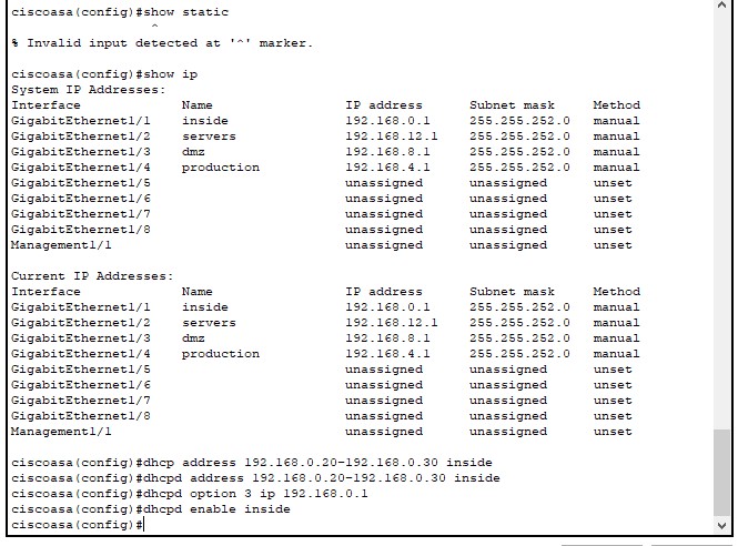
Overview of the specified interfaces and their networks